Week 1
Mech
We started the semester with talking about our first assignment, which is to model a mech (robot), texture it, rig it and apply Motion Capture data to it. The first step was to do some research and save reference material.


After researching, we started to model. As we intended to apply motion capture data to the finished rigged model, we had to keep size proportion and also model a human-like robot and not something with knees that bend backwards for example.
To get the right height I made a box with 180 in height because in Maya 1 unit equals 1cm. To get an even better 'cheatsheet' i imported a human proportion image as an imageplane and adjusted the height to be the same as my height-reference box.


I've only managed to model a foot and a lower leg in class because the foot didn't work out as I imagined it would.
30.01.2018
Week 2
UV Mapping
Before we can import our material into Substance Painter we have to UV Map it, otherwise the texture will come out distorted and wrong. With the new 3D Cut and Sew UV Tool you can cut along all the edges to basically flatten the 3d object in multiple 2d shapes. After cutting and selecting the UV-Shell, pressing 'D' will flatten the shell. Activating the checkerboard will give you a preview if the UV Map works. If the checkerboard looks proportionally correct on the whole object the UV Map works.

If you go to the Layout UVs Options in the UV Editor and change Shell Pre-Rotation to Vertical and Shell Pre-Scaling to Preserve 3D Ratios Maya creates a perfectly proportional UV Map for you.

This video demonstrates the above-described use of the 3D Cut and Sew tool. At the end of the video, the automatic layout doesn't work at first because I'm still in the cut and sew tool and haven't selected all of the UVs but I got there in the end.

Substance Painter

The last step before importing the object into Substance Painter after UV Mapping it is to apply the Arnold aiStandardSurface Material and name the Material. Then simply click on the object you want to export and go to File --> Export Selection (or just Export if it's just one object) and export it as .fbx.
In Substance Painter just go to File --> New, select PBR - MEtallic Roughness HQ (allegorithmic) as Template and select your exported .fbx file as your Mesh.

After importing the object, just select one of the Smart Materials, drag it up to Layers and click on Bake textures. After baking it gives you a preview of how the object will look. If you're happy with the texture, go to File --> Export Textures, choose Arnold 5 as config and set the path to your project folder. This will create multiple texture files. This is where you need to place each file:
Base --> Color = BaseColor
Base --> Metalness = Metalness
Geometry --> Bump Mapping = Normal
Specular --> Roughness = Roughness
inside Roughness go to Colorbalance --> Alpha is luminance = on
This is a video of how to import an object, apply, bake and export the finished texture. There's a glitch in the big front dent which I fixed with inserting an extra edgeloop.
This is my model so far, which I now need to UV Map

06.02.2018
Week 3
Substance Painter - in Depth


This week we had an in-depth look at Substance Painter to create a material for our robot. After a while of playing around with the many many settings, I chose this as my main material. It's an aluminium base combined with the 'Super Hero Fabric' to get a kind of chequer plate. The black fabric that's coming through to make it look like a used/old robot is black plastic rubber. The idea behind this combination is to make the main parts of the robot look light (plastic didn't look as good).
The last part to finish my texture is to use the Sand Storm particles to make the object look even more used. I use this on each part individually to create a more random look.
Close up look at the fabric structure. I sprayed an X on the leg as an extra bit which is saved in Layer 1. As I don't want that on all of my parts I just disable Layer 1 on all of my other parts when applying this material.
After creating the texture I grouped all of it and named it, then I was able to right-click it and save it as a smart material so I didn't have to create the same texture for every object. You can even export the texture by right clicking --> export so you can save it and use it at home or the next time on another machine.
In this video, you can see how to import the texture the next time.
This video demonstrates an easier approach to UV mapping. Just go to UV --> Automatic and it creates an almost perfect UV-Map for you. This works most of the time but if it doesn't, you can still edit the UV-map after.
Quick Render to show how the material looks like beeing used. The lightning isn't great but this is just a quick preview.


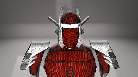
This shows my progress so far. I'm not sure if I'll keep the head as it is and the main body needs a bit refinement.
13.02.2018
Week 4
The major part of Week 4 was a workshop session, but we also looked at rigging and blendshapes. This is a close up of my upper arm where I tried to create the look of a damaged part that has been replaced with a new material as a kind of quick-fix-patch.

This is a demonstration on how to create blendshapes in Zbrush and import them into Maya. The export out of ZBrush didn't work in the end but after clicking on Maya Blend Shapes it should just export it into Maya and that's it.
I have now textured almost everything besides the head. I changed the shoulder plates because they restricted the movement of the arm too much.

20.02.2018
Week 5


Week 5 was another workshop class where we all worked on our assignment and could ask for any help if needed. I used the time to texture the last few body pieces and also to remodel the head. The first version wasn't really what I wanted it to become so I changed the sides a bit and it already looks a lot better now. The 'filter' on the side was actually a hole in my model which I wasn't able to close so I filled it with this filter/ventilation and I worked out really well.
I textured the glasses with a glass material in Substance Painter and used a brush and the 'glass-shatter' particle to give it a scratched and/or 'something-hit-the-glasses' look .

The rest of the head/helmet is just a mix of my other materials.


Here are a few quick renders of my finished robot. The lightning isn't really great, but you can see a few of the details. you can also see that my white painted steel material isn't supposed to look so ruff, but maybe that's also because of the light.


In the top image, I forgot to tick 'Luminance is alpha' in the Specular --> Roughness settings. This is a good example to show what a big difference this setting makes.
Rigging
After I finally finished my modelling and all the texturing I rigged my character. At the end of this video I realise that I parented my arms with the neck rather than my spine.
X-Ray view to show the rig


After parenting the Mesh I realised that my Rig isn't working. With the arms parented to the neck they are always moving if the neck moves, which isn't how it's supposed to be. I parented the arms to the last part of my spine which is usually higher for a human, but how I built my robot it's the only way possible and most important it works now.
I also had to add another joint as my hips because I was one short.


Motion Builder naming convention
As we intend to apply motion capture data to our robot to bring it to life it is important to follow the naming convention that Motion Builder uses to allow an easy workflow.
My robot is now ready for motion capture data to be applied. This is just a quick animation to show that the rig works properly.
27.02.2018
Week 6


Binding Skin
We started looking at binding skin today where you can connect mesh to a rig. We modelled an arm out of one object as an example and created a rig for it. After changing the pivot point and shift selecting the rig and the object you can go Rigging Tab --> Skin --> Bind Skin Options.

Make sure to select Geodesic Voxel as Bind method and click Bind skin.
If you're not happy with how the mesh bends after binding the skin you can change it in the pose editor as shown in this video.
06.03.2018
Week 7
Controllers/Constraints
Week 7 was dedicated to further Rig development. We started with adding different layers for Rig and Skeleton to get a better overview and then did a quick recap of IK Chains and how to parent controllers to them.
Pole Vector: To create a knee controller you need to create a nurb controller --> shift select IK chain ankle --> Constraint --> Pole Vector
Point Constraint: For the hip controller I created a nurb controller that is visibly different from the other controllers and froze the transformation, then Constraint --> Point constraint, Constraint --> Orient options --> check on maintain offset --> apply.
Aim Constraint: For the eye I created a visible different curb controller again and then clicked Constraint --> Aim Constraint options --> check on maintain offset --> apply.
13.03.2018
Week 8
Week 8 was a continuation of Rigging techniques. We started with the Connection Editor which you can find at Windows --> General Editors --> Connection Editor. In there you can select two points of your rig and connect the x-axis rotation for example. This way you only have to rotate the base but the rest of the rig gets affected as well like I've demonstrated in this video.

The next thing we looked at was Set Driven Key which can be found at Animation Tab --> Key --> Set Driven Key --> Set. Here you can choose which object you want to driven by another object.

After that you choose what you want to move from the driver and what you want to be moved from the driven. Click Key on your base positions, move the objects and click Key again. In the video above you can see ball is being affected by the rig.
In this video I just had a play around with driven keys.
This video demonstrates how to create a Aim Constraint to create something like a piston for example.
The last thing we looked at was the Spline IK which can be found in the Rigging Tab at Skeleton --> Create IK Spline Handle. After that you select the bone you want the IK Spline to start and the one you want it to end and it creates a curve for you. To be able to affect this curve and parent controllers to it you need to right-click on the actual curve --> Control Vertex and then click on the two little points that pop up and go Deform --> Cluster. With the clusters you can know parent controllers to it to affect the curve.
20.03.2018
Week 9 + 10
Week 9 & 10 were Course Based Activity weeks which means no class
Week 11

After the two coursed based activity weeks we started working on our last assignment, rigging an elephant. This is the elephant we got with only a controller for the eyes at the moment that isn't connected to anything.

The first thing we did was to create an aim constraint for the eyes, so the eyes follow the controller when moved. The second thing we were shown was to create a blend shape to make the eyes blink. To create a blend shape you need to go to Windows --> Animation Editors --> Shape Editor. Select the Elephant
and click Create Blend Shape. Next click Add Target and start moving the faces of the eyelid into the position you want it to become when the eyes are closed. If you're happy with the position of the eyelid click on Edit so it becomes grey which means it's not recording anymore.
If you want to put the blend shape in the channel box of the eye-controller so everything about the eyes is in one place you can go Channel Box --> Edit --> Add Attribute and enter the name you want it to have. Then go Windows --> Animation Editor --> Expression Editor. You have to type the blendshape first and then where you want it to be controlled from in this format: NameOfBlendshape = NameOfHandle. For the example in the video, it would be eyelid.blink = Eyes_Ctrl.eyelid_blink and click Create. The last step is to edit the attribute in channel attribute and enable minimum/maximum and keyable.
After that, we were on our own. After researching elephant anatomy and watching videos of how elephants walk I started creating a rig for the legs, spine and tale.

10.04.2018
Week 12/13/14/15

The rest of the semester was workshop classes where we could work on our assignment and ask for help if necessary.
After creating the rest of the rig for the elephant I started to create controllers for the feet. I put IK Chains in the feet and parented the controller to them. Controller 1 moves the whole foot, controller 2 bends the toes and controller 3 bends the 'ankle'. I chose 3 controllers for the feet because if someone potentially animates this elephant, having multiple options to move/bend the feet is important to make the walk look realistic. The knee controllers are Pole Vectors.

I created a spline IK for the trunk because it seemed a good way to move it accurately. I had a bit of a problem at first because turning off my Skeleton layer also turned off the curve I needed to rick-click --> control vertex to deform them to a cluster.

The two controllers for the mouth are Orient Constraints, the ear and neck are spine IKs and the overall head controller is just parented (that's also why this controller is blue, if I'd change the colour it would change the colour of the head skeleton). I chose spline IKs for most of my rig because I like the freedom of movement it gives you. I tried to combine the ear rig with the connection editor so I would have one controller which moves the whole ear but it didn't work out as well as I'd hoped.

The spine and the tale are spline IKs again and the hip controller is a point and an orient constraint. At first, I started the spline IK for my spine at the hip joint which constrained it and made it unmoveable so I had to start the spline IK one joint after the hip.
The last part was to skin the elephant to the rig and paint skin weights. I don't know why but skinning messed up all my spline IKs. I had to connect all the controllers back to the clusters. The painting weights helped move the skin more accurately when moving the rig. I mainly used it for the mouth, tale and ears.

Before

After


This is my final rig.

This is a demonstration of how the rig works. I also put a driven key in that lifts the elephant by moving a box just to show driven keys again.
08.05.2018